LED Sousaphone Bell
Note
Check out Jay Converse’s and Jon Swope’s LED bells too!
//—Under Construction—//
Planning the Pattern
Any pattern of LEDs can work as long as their X,Y coordinates are known.
Whole strips of LEDs can be placed as “lines”, or individual LEDs can be cut as pixels.
Software such as MaxMSP can create a pattern of white dots on a black background, and output a list of their coordinates. This image can be projected onto a sousaphone bell to illuminate the positions of the LEDs, but be careful not to mirror the image.
The OctoWS2811 adapter for the Teensy microcontroller supports eight strings of LEDs. Thus, you can place eight strips, or, if you placed individual LEDs, you must stare at the illuminated LED sousaphone bell with great intensity and discover the best way to connect the dots with eight separate paths that all start at the edge of the bell.
If you placed individual LEDs, then stick each LED to the bell in the eight separate paths that you’ve discovered.
The LEDs are uni-directional, so be sure not to place them backwards.
For instructions on how to connect the OctoWS2811, Teensy, power supply, and LEDs, Click here.
Mapping the LEDs
ws2812b LEDs are what’s known as “individually addressable”, meaning they can be sent a list of unindexed RGB data and they will automatically sequentially assign each piece of RGB data to each LED in the string.
The OctoWS2811 adapter automatically separates an incoming list of RGB data for each string according to the ledsPerStrip and numStrips variables in the Teensy’s code.
To efficiently calculate this list of RGB data every frame, each LED has data in four separate arrays for their X values, Y values, distances from the center, and angles from the center. This data must be laid out in the same order that the LEDs are wired, which may take some wrangling to accomplish.
Jason Coon’s LED Mapper website can assist in calculating the distance and angle from center, given the coordinates. Or you can calculate it yourself with trigonometry.
Color pallettes are stored as arrays of RGB data, which can be interpolated and cycled through over time. The methods of cycling through pallettes based on the LED data are known as a patterns, which look like this:
void clockwisePalette()
{
  for (uint16_t i = 0; i < NUM_LEDS; i++)
  {
    leds[i] = ColorFromPalette(currentPalette, params.gradientOffset + angles[i]);
  }
}

   void outwardPalette()
{
  for (uint16_t i = 0; i < NUM_LEDS; i++)
  {
    leds[i] = ColorFromPalette(currentPalette, params.gradientOffset - radii[i]);
  }
}

void northEastPalette()
{
  for (uint16_t i = 0; i < NUM_LEDS; i++)
  {
    leds[i] = ColorFromPalette(currentPalette, params.gradientOffset - (coordsX[i] + coordsY[i]));
  }
}
Every frame, the chosen pattern will loop through every LED and calculate its RGB value based on the chosen palette and the given LED coordinate, radius, and/or angle data.
//-–Under Construction—//
Old Tutorial (superseded)
by John Baylies - sousastep.quest
Materials
One dedicated sousaphone bell (this is a permanent installation) I used a fiberglass bell spray-painted black. the LEDs will stick to a lacquered bell just as well, but keep in mind that the LEDs will be soldered while they’re on the bell, which would not do the lacquer any favors.
Condenser clip-on mic. My max patch currently only uses amplitude data from the mic. It’s definitely possible to use a much cheaper mic, or even solder your own.
Teensy 3.2 A Teensy 4 will work as well.
Note
(200 LEDs needed for this tutorial, but definitely buy extras. Even the pros sometimes have trouble sourcing good ones that won’t burn out quickly) WS2812 LEDs were released to the world 7 years ago, and they’ve been improved upon since then. Click here to read more about other types of LEDs.
Note
After four years of using this PSU I just had an issue where, a few times an hour, my LEDs would all turn off for a minute. Unplugging the PSU from the outlet and plugging it back in fixed it. It had been plugged in for months so maybe just don’t leave this PSU plugged in for weeks on end.
Soldering Iron (I bought a cheap soldering iron, hated it, then splurged on the Weller, which is great)
lead solder (leadless solder is a PITA)
Note
If you haven’t soldered before, Nic Collins’ book Handmade Electronic Music is a great way to learn. Also, Adafruit has a soldering guide specifically for LEDs.
Important
DON’T BREATH THE FUMES! IT’S LEAD!
Electrical tape and Gorilla tape
Projector and tripod (the tripod matters more than the projector. It must remain completely stationary for however long it takes you to place all of the LEDs on the bell)
Overview
Max/MSP handles the VFX, and outputs a stream of RGB data to the Teensy, which uses the venerable OctoWS2811 to send RGB data to the ws2812b LEDs. Max must ensure that the RGB data is sent to the Teensy in the order in which the LEDs are wired to the OctoWS2811. Sometimes this stream of RGB data can become offset. To fix this we add start and end markers to each frame of RGB data .
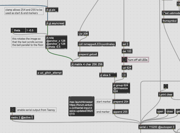
Since Max can only send the numbers 0 - 255 to the Teensy, we clamp 0 - 253 so that 254 and 255 can be used as markers. There’s not much of a difference in brightness at that end of the range, anyways.
The current Teensy code can be downloaded from here. Last time I touched this code I was messing with an accelerometer and a capacitive touch sensor, and couldn’t get them to work well, but haven’t removed the code yet, so there’s some superfluous code in there.
You can download my VFX Max project here (with the start and end markers). It’s set up to work with my rig, so you may want to extract the serial stuff and build your own rig around that.
Initial Setup
Start with the simplest possible setup to ensure that Max can control the LEDs before they’re attached to the bell.
Click here for instructions on how to connect the OctoWS2811, Teensy 3.2, power supply, and LEDs.
Download this folder o’ files. (without start and end markers)
Upload success.ino to the teensy by following these instructions.
Open testpatch1.maxpat
Turn the patch’s audio on.
Clear the serial ports and locate the teensy.
Enable jit.world, and the LEDs should light up…
If only some of the LEDs light up, change this portion of the code:
const int ledsPerStrip = 26;
const int numStrips = 8;
Getting the Coordinates
We can get a list of RGB data from Max by sending pixel coordinates to a matrix. You can arrange the LEDs in any pattern you’d like as long as there’s an ordered list of coordinates, which will have to be reordered after the LED wiring order is determined.
Here’s how I got the coordinates for remappedLEDcoordinates.txt
I found this website, clicked “table”, selected the first 200 coordinates, copy-pasted them into google sheets, exported the sheet as a csv file, and used Justin G’s max patch to convert the csv file into Max’s coll object.
then,
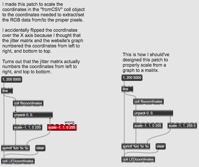
This patch will get the Fib. Spiral showing up properly in jit.world
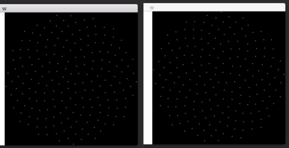
Left, incorrect, flipped on x-axis. Right, correct. (challenge: turn the coordinates 90 degrees. It’d look more symmetrical.)
Arranging the LEDs
Project a screenshot of the spiral in jit.world onto the bell. Place the LEDs onto the projected dots while being mindful of the wiring order. You’ll want to wire the 200 LEDs in eight groups of 25. You should use your own discretion to do this as efficiently as possible.
One problem I faced is that I placed half the LEDs, then took a break for a few days, and when I tried to set up the projector again I learned that realigning the projector perfectly is impossible. This led to one speck of light hitting the flare of the bell the first time, and the throat of the bell the second time, which made me place one extra LED, which led to much confusion later on.
Once completed, the bell will look best from the projector’s point of view.
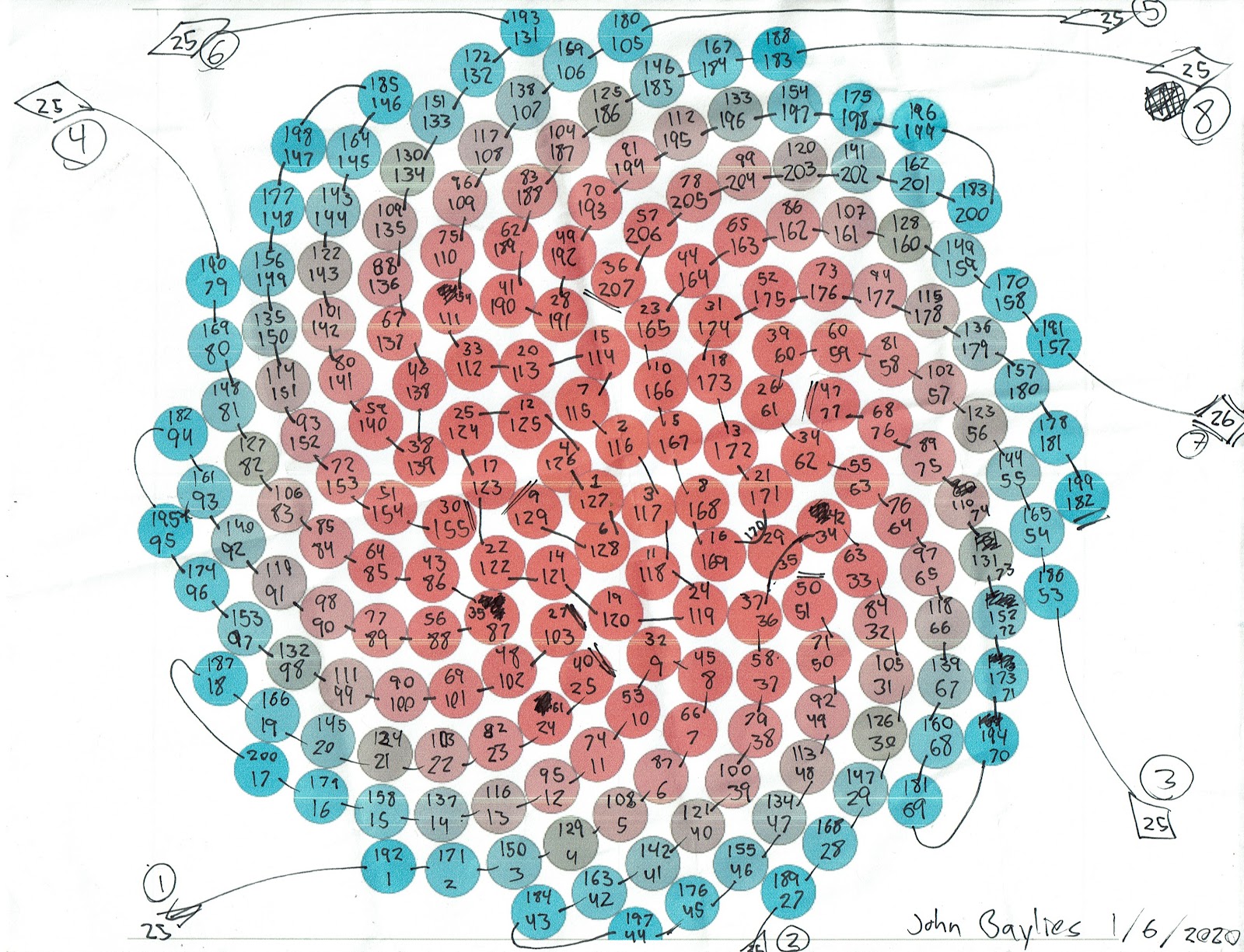
I used this diagram to reorder the coordinates from the Fibonacci spiral order to my wiring order. You can use it as a guideline, but be warned that it’s flipped on its X axis, and I had to account for one extra LED. Fibonacci index #29 corresponds to wiring index #35 and #170.
The top numbers are the Fibonacci indices, from iwant2study.org. The bottom numbers are the wiring indices, which can be determined by turning on the first LED in each of the eight strips.
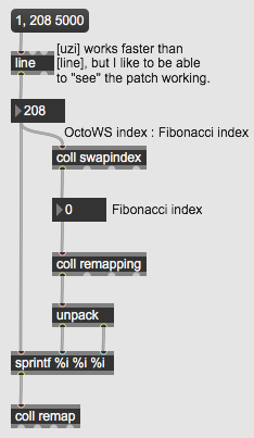
Typing those indices into a coll object allows the coordinates to be reordered using the patch below.
This essentially makes the whole thing a big, low-resolution TV screen.
Thanks
Many thanks to the Brooklyn College Sonic Arts program and the Performance And Interactive Media Arts program.